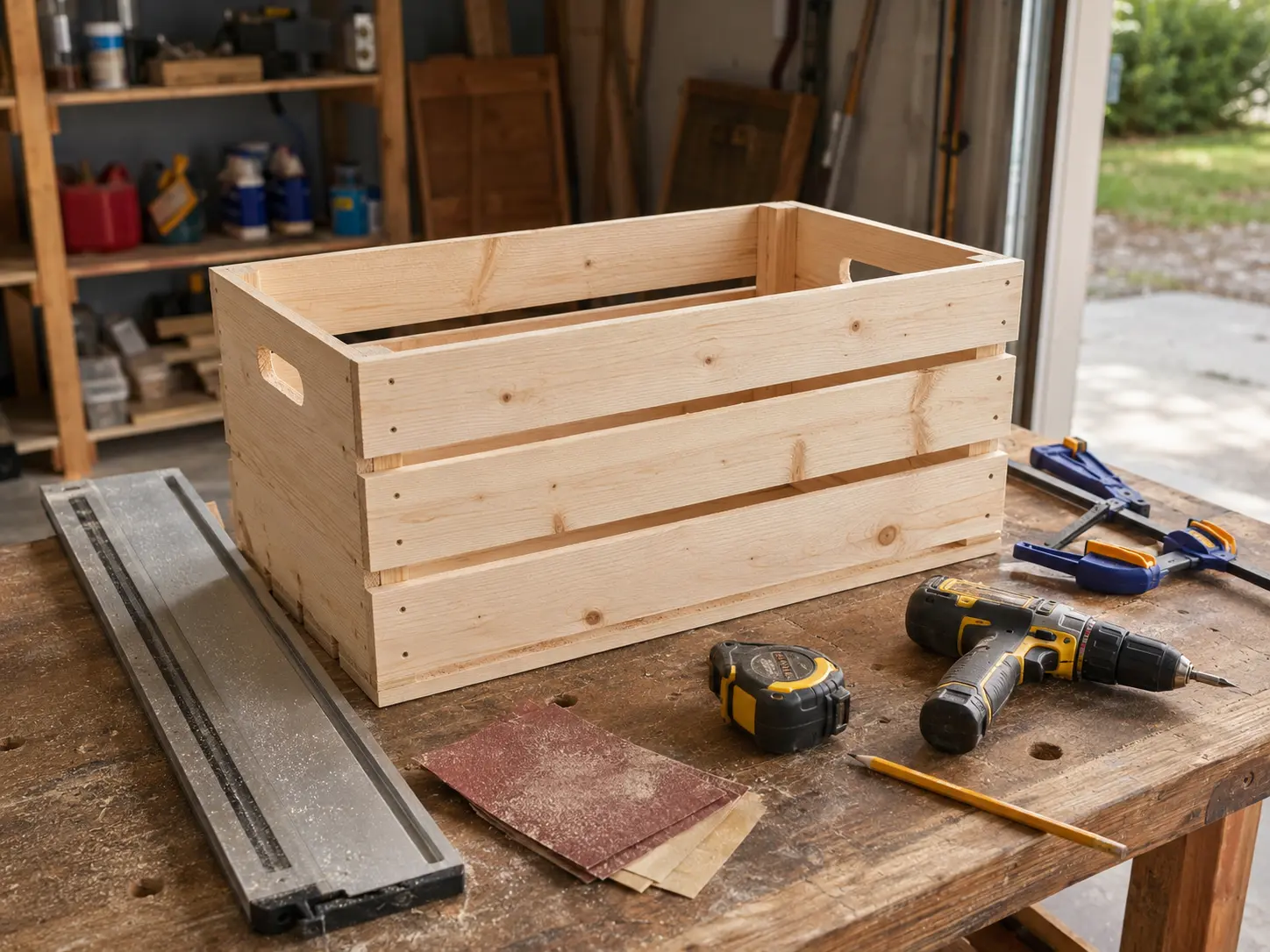
What Should a Good Woodworking Plan Include? 12 Essential Parts
A good woodworking plan should include finished dimensions, intended use, a complete material and hardware list, a detailed cut list, realistic tool requirements, dimensioned drawings, joinery details, an ordered build sequence, finishing or installation instructions, limitations and revision information. Most importantly, the lists, drawings and instructions must agree with one another.
A polished rendering is not enough. Before buying lumber or making the first cut, you should be able to answer three practical questions:
- What exactly am I building?
- Do I have the materials, tools and ability to build it?
- Can I verify that the parts and steps produce the stated result?
This guide gives beginners a repeatable way to inspect a free, paid or AI-generated woodworking plan. It does not certify a design's structural capacity, code compliance or safety.
The 12 essential parts of a good woodworking plan
| Part | What the plan should tell you | Why it matters |
|---|---|---|
| 1. Project overview | What the project is, where it will be used and who it is for | Defines the design problem |
| 2. Finished dimensions | Overall height, width and depth | Confirms that it will fit |
| 3. Units and assumptions | Units, dimension order, nominal versus actual sizes and material condition | Prevents silent measurement errors |
| 4. Bill of materials | What lumber, panels, hardware, adhesive and finish to buy | Makes the shopping list complete |
| 5. Cut list | Every finished part, quantity and size | Defines the components to make |
| 6. Cutting diagram | A possible layout on boards or sheet goods, when useful | Helps estimate stock and waste |
| 7. Tool requirements | Required tools, accessories and optional substitutes | Tests whether the plan fits your shop |
| 8. Dimensioned drawings | Views, part labels, dimensions and useful details | Shows how parts relate |
| 9. Joinery and hardware | Joint geometry, fastener specifications and placement | Makes connections buildable |
| 10. Assembly sequence | Steps in a workable order | Prevents one operation from blocking another |
| 11. Finish and limitations | Surface preparation, installation, environment and use restrictions | Defines how the project is completed and used |
| 12. Version and support | Date, revision number, corrections and contact route | Helps you identify current information |
Not every simple project needs a long document. A small shelf may be explained with one drawing, one cut list and a short sequence. Complexity should determine length—but simplicity does not excuse contradictory or missing information.
1. Project overview and intended use
The opening should define the finished object in plain language. “Outdoor storage bench” is more useful than “weekend build” because it begins to establish location and function.
Look for:
- the project's intended use;
- indoor, covered outdoor or exposed outdoor placement;
- the intended user or application, when relevant;
- the primary material and construction method;
- an honest difficulty level;
- approximate build time, if provided, with assumptions;
- important limitations.
Difficulty labels are subjective. “Beginner” should not be the only evidence that a project is suitable for you. Inspect the actual operations and tools.
For projects that support people, span openings, carry substantial loads, attach to a building or fall under local building rules, a general woodworking plan may not provide adequate engineering. The plan should state the assumptions behind any capacity claim instead of presenting an unexplained number.
2. Finished dimensions
A plan should state the project's overall finished height, width and depth near the beginning. These dimensions help you check the intended location before material is purchased.
Measure the real space, including:
- baseboards and trim;
- door swings and drawer travel;
- access for installation;
- floor or wall irregularities;
- clearance around heat sources, outlets or equipment;
- the route required to carry the assembled project into place.
The overall dimensions should agree with the detailed drawing. If a cabinet is listed as 30 inches wide, the sum of its side, opening and divider dimensions should explain that width. A conflict at this level is a reason to pause—not an invitation to choose whichever number looks more plausible.
Tolerances should match the project
Some dimensions are critical; others can vary. A drawer width, door reveal or joint shoulder may need tighter control than the length of a rough outdoor planter.
A useful plan identifies dimensions that must match an existing part, opening or piece of hardware. Better plans also explain when to measure the project itself instead of relying blindly on a printed number.
3. Units, dimension order and material assumptions
The plan should establish its measurement language before the cut list begins.
Check for:
- U.S. customary units, metric units or both;
- whether dimensions are written as thickness × width × length;
- fractions or decimals used consistently;
- rough, nominal or finished dimensions;
- actual material thickness after surfacing;
- plywood thickness assumptions;
- moisture or material condition when it affects the build;
- whether templates are full size or must be scaled.
Nominal lumber names are not finished measurements. Under the U.S. softwood lumber standard, a nominal 2 × 4 is a size classification, while the familiar minimum dressed dry size is 1-1/2 × 3-1/2 inches. A plan that uses construction lumber should make clear whether a number is nominal or actual rather than forcing the builder to infer it. See the NIST American Softwood Lumber Standard.
Plywood and project boards also need verification. Measure the stock you will use before cutting joinery that depends on its thickness. A dado labeled 3/4 inch may not fit a panel sold under that nominal description.
4. A complete bill of materials
The bill of materials, or BOM, describes what to obtain. It should include more than lumber.
A useful BOM may list:
- lumber species, grade or acceptable alternatives;
- nominal and actual sizes where necessary;
- rough purchase lengths and quantities;
- sheet-good type, grade and thickness;
- screws, bolts, washers, nuts and nails;
- hinges, slides, brackets, knobs or other hardware;
- adhesive type;
- abrasives;
- finish or protective coating;
- project-specific consumables.
Hardware needs an identifiable specification. “Screws” is incomplete when the length, gauge, head style or corrosion resistance affects the connection. “Hinges” is incomplete when the door geometry depends on a particular hinge type.
The BOM should also distinguish between project material and shop supplies. A builder may already own glue and sandpaper, but those items still affect readiness and cost.
Material substitutions need consequences
“Use any wood” is rarely complete guidance. Changing species, thickness or panel type can affect weight, movement, joinery, fastener choice, finish and cost.
A good plan does not need to cover every possible substitute. It should identify which material properties the design assumes and which dimensions must change if the material changes.
5. A detailed cut list
A cut list describes the finished parts to produce. Each row should normally provide:
- part name or ID;
- quantity;
- thickness;
- width;
- length;
- material;
- orientation or special notes when relevant.
The U.S. Forest Products Laboratory similarly emphasizes that quantity, size, species or material and whether dimensions are nominal or actual must be clearly defined when specifying lumber. See its chapter on commercial lumber and dimension stock.
Part names should match the drawings and instructions. If the cut list says “B — left side,” the assembly steps should not call it “panel 3” without a clear mapping.
Final sizes are not always first-cut sizes
A cut list may show final dimensions even when a part should initially be cut oversized for milling, matching or trimming. The plan should say so.
Dependencies matter. A rail may need to be cut to fit the actual distance between two assembled legs. A drawer component may depend on the installed slide and measured opening. In those cases, “measure after assembly” can be more accurate than a fixed number.
Do not cut every part automatically just because the plan provides a list. First identify fit-dependent parts and read the sequence.
Bill of materials vs. cut list vs. cutting diagram
These are different documents:
| Document | Core question | Typical contents |
|---|---|---|
| Bill of materials | What do I buy? | Boards, sheets, hardware, adhesive, finish and quantities |
| Cut list | What finished parts do I make? | Part names, counts, dimensions, materials and notes |
| Cutting diagram | How might I lay those parts out on stock? | Part placement, sheet or board boundaries, grain and cut order |
A BOM might tell you to buy two 8-foot boards. The cut list might require four 22-inch rails and four 16-inch legs. A cutting diagram proposes how those parts could come from the available boards.
One cannot safely replace the others.
6. A realistic cutting diagram when it adds value
Cutting diagrams are especially useful for plywood projects, repeated parts and material estimates. They should account for:
- blade kerf;
- trimming or squaring allowances;
- grain direction and visible faces;
- sheet orientation;
- defects in real boards;
- safe support and manageable cut order;
- matched color or grain when appearance matters.
A digital layout is an estimate, not a command. Real lumber contains knots, cracks, bow and color variation. Your actual blade has a kerf, and a full sheet may need to be broken down differently to remain safely supported in your workspace.
Be skeptical of a diagram that packs parts edge-to-edge with no kerf or trim allowance. Also be skeptical of a “zero-waste” claim that ignores defects, grain direction or the cuts needed to establish straight reference edges.
7. Required and optional tools
The tool list should reflect the instructions—not merely the main cuts.
Look for:
- required power tools;
- hand tools;
- blades, bits and accessories;
- measuring and marking tools;
- clamps and their necessary capacity;
- sanding and finishing equipment;
- safety equipment;
- optional tools clearly marked as optional;
- tested alternatives, when offered.
“Drill required” may be insufficient if the build needs a Forstner bit, countersink, pocket-hole jig or right-angle access. “Circular saw required” does not tell you whether the plan assumes a guide, a fine-tooth blade, bevel capacity or a safe way to support a large sheet.
Compare every operation in the instructions with the initial tool list. A router, nailer or special jig that first appears halfway through the build is a hidden requirement.
A tool alternative must preserve the operation
An alternative is credible when it explains how the same result will be controlled and measured. “Use any saw” is not enough if the operation requires repeatable identical parts or a precise groove.
Never remove or defeat a tool's guard because a drawing or jig conflicts with it. Follow the tool manufacturer's instructions. OSHA's woodworking guidance illustrates why guarding and point-of-operation control matter, although its workplace rules are not a substitute for the manual for your particular tool. See OSHA woodworking machinery requirements.
8. Dimensioned drawings that answer build questions
Useful drawings communicate geometry, not just appearance. Depending on the project, the plan may need:
- an overall view;
- front, side and top views;
- an exploded view;
- sections through hidden joinery;
- enlarged details;
- hole and hardware locations;
- part IDs that match the cut list;
- a declared scale for templates;
- orientation marks for left, right, front, back, inside and outside.
Every important dimension should have a clear origin. A hole location needs reference edges. A centered part should be labeled as centered or dimensioned from a known face. Repeated spacing should state whether the number is on-center, edge-to-edge or a clear gap.
Do not measure a screen image
Unless a drawing is explicitly supplied at a reliable scale and printed correctly, use its written dimensions. Browser resizing, printer settings and PDF scaling can change the apparent size.
For a full-size template, the plan should provide a calibration mark or known dimension so you can confirm that it printed at 100 percent.
9. Joinery and hardware details
“Attach the sides” is not a joinery instruction.
The plan should define, where relevant:
- joint type and dimensions;
- reference face and orientation;
- glue surfaces;
- fastener type, length and placement;
- pilot-hole and countersink requirements;
- edge distances;
- hardware model or critical geometry;
- alignment method;
- clamping strategy;
- whether a connection must remain removable.
The drawing, BOM and steps should agree. If eight bolts appear in the exploded view, eight compatible bolts—and their washers and nuts—should appear in the material list and installation steps.
Adhesive and finish directions should defer to the product label for suitable materials, application conditions, open time, cure time and protective measures. A plan should not silently generalize one manufacturer's instructions to every product.
10. An ordered assembly sequence
Correct parts can still produce a difficult build when the sequence is wrong. A usable plan arranges operations so that each step leaves access for the next.
The sequence should address:
- stock preparation;
- layout and reference marks;
- parts that should be cut or drilled together;
- dry fitting before glue;
- subassemblies;
- sanding before access becomes restricted;
- glue-up and clamping order;
- squareness checks;
- hardware installation;
- finish timing;
- final adjustment and installation.
Read the entire sequence before starting. Ask whether a drill, driver, clamp or brush can physically reach the location at the specified time. Check whether installing one panel covers the fasteners for another.
A strong plan includes checkpoints such as “confirm both diagonals are equal before the glue sets” or “fit the drawer after the case is assembled.” These checks catch accumulated error while it can still be corrected.
11. Finish, installation and use limitations
A project is not complete when assembly ends. The plan should explain the intended path to a usable result.
Relevant information may include:
- sanding sequence or target surface preparation;
- edges that should be softened;
- finish compatibility with the intended environment;
- surfaces to finish before assembly;
- cure time based on the chosen product's instructions;
- wall, floor or structure attachment;
- leveling and adjustment;
- ventilation and disposal precautions from product labels;
- indoor or outdoor limitations;
- maintenance expectations.
Installation details are especially important for wall-mounted projects. The plan should state the mounting concept and assumptions, but the builder must still identify the real wall construction, utilities and suitable fasteners.
Load and use claims require evidence
Do not infer a load rating from a photograph. A shelf, bench, loft, play structure or building component can fail even when it looks substantial.
A responsible plan should not invent a capacity. If load, anchoring or code compliance is important, look for stated design assumptions, qualified review, applicable standards and local requirements. This checklist can reveal missing evidence; it cannot supply engineering that the plan lacks.
12. Version, corrections and support information
Plans can contain errors. What matters is whether the publisher identifies and corrects them transparently.
Look for:
- publication or revision date;
- version number;
- change log or correction notice;
- a route for reporting an error;
- an identifiable author or publisher;
- access terms for future updates;
- support scope and response expectations, if support is sold.
If a correction exists, confirm that your cut list, drawings and instructions are all from the same version. A revised diagram paired with an older cut list can create a new contradiction.
The Plan Integrity Triangle
The fastest way to detect a weak plan is to cross-check its three operational layers:
Drawings ↔ Cut list ↔ Assembly sequence
Each layer should confirm the other two.
| Cross-check | Question to ask |
|---|---|
| Drawing ↔ cut list | Does every labeled part appear with the same quantity and dimensions? |
| Cut list ↔ sequence | Is every part used, and are fit-dependent parts cut at the correct time? |
| Drawing ↔ sequence | Do the stated connections, orientations and hardware match the visual? |
| BOM ↔ all three | Can every material and hardware item be traced to a part or operation? |
| Tool list ↔ sequence | Is every operation possible with the tools and accessories disclosed? |
A beautiful drawing cannot rescue a wrong cut list. A perfect cut list cannot rescue an impossible assembly order. Internal agreement is the minimum standard.
How to audit a woodworking plan in three passes
Do not try to check everything at once. Use three passes, moving from broad fit to detailed readiness.
Pass 1: Feasibility
Decide whether this is the right project for your situation.
- Does the finished project fit its location?
- Is the intended use clear?
- Are the material cost and availability realistic?
- Do you have space to handle the stock?
- Do you own, borrow or rent the required tools?
- Are the unfamiliar operations reasonable for your skill level?
- Does the project involve structural, electrical, plumbing or code questions beyond the plan?
If the answer is no, stop before investing time in dimensional checks. A technically complete plan can still be a poor fit.
Pass 2: Internal consistency
Cross-check the documents.
- Recalculate the main overall dimensions from the parts.
- Match every drawing label to the cut list.
- Count repeated components.
- Trace every hardware item into the BOM and sequence.
- Compare joint dimensions with actual material thickness.
- Confirm left/right and inside/outside orientation.
- Check that the cutting diagram includes all parts.
- Identify parts whose final size depends on assembly.
Do not “average” conflicting numbers. Mark the conflict and resolve it with the publisher, a correction or your own verified redesign.
Pass 3: Build readiness
Turn the plan into an executable preparation list.
- Measure the actual material.
- Confirm blades, bits, guides, clamps and safety equipment.
- Read the manuals and labels relevant to each operation.
- Mark critical dimensions and reference faces.
- Note dry-fit and squareness checkpoints.
- Plan safe sheet and board breakdown.
- Separate finish-before-assembly parts.
- Confirm hardware fit with a sample or scrap setup.
- Print or save the exact plan version you audited.
Only after this pass should the project be treated as ready to start.
Red flags: stop before cutting
Pause and resolve the issue if you find any of these:
- overall dimensions conflict with the component dimensions;
- part totals do not produce the stated size;
- a drawing shows parts missing from the cut list;
- hardware appears in a drawing but not in the BOM;
- a required tool or accessory appears only in later instructions;
- nominal and actual material sizes are mixed or unclear;
- left/right, front/back or inside/outside parts are not identified;
- the cutting diagram ignores grain direction, kerf or real stock condition;
- the sequence closes access needed for a later step;
- a template has no scale check;
- load or safety claims have no stated basis;
- the plan relies on attractive renderings but lacks fabrication detail;
- a correction is announced without identifying the revised version.
One small typo does not necessarily invalidate a plan. Multiple unresolved contradictions do. The goal is not to punish imperfect documentation; it is to avoid transferring its uncertainty directly into your material.
How should you evaluate an AI-generated woodworking plan?
Treat an AI-generated plan as an unverified design draft, not as construction authority.
Text and image tools can help organize ideas, explore dimensions or produce a preliminary parts list. They can also return confident-looking numbers that do not add up, impossible joints, inconsistent part counts, missing hardware or operations that the stated tools cannot perform.
Before using an AI-generated plan:
- Define the intended use and constraints yourself.
- Recalculate every overall dimension.
- Rebuild the BOM from the verified parts.
- Match every cut-list row to a labeled drawing part.
- Check actual material thickness and hardware geometry.
- Confirm that each operation is physically possible and safely supported.
- Rewrite the assembly order if access becomes blocked.
- Prototype unfamiliar joints or critical fits with scrap.
- Reject invented load ratings, code claims or unsupported safety assurances.
- Obtain qualified guidance when structural performance or code compliance matters.
Prompt refinement is not verification. Asking the same system to “double-check” its own answer may improve the draft, but it does not replace independent measurement, calculation, manufacturer documentation or appropriate professional review.
Printable woodworking plan evaluation checklist
This table is designed to print cleanly from the page. Use the notes column for conflicts and questions.
| Check | Verification question | Status | Notes |
|---|---|---|---|
| Intended use | Is the purpose and environment clear? | ☐ | |
| Finished size | Will the project and installation route fit? | ☐ | |
| Units | Are units, dimension order and precision consistent? | ☐ | |
| Material sizes | Are nominal, actual, rough and finished sizes distinguished? | ☐ | |
| BOM | Are lumber, sheet goods, hardware, adhesive and finish included? | ☐ | |
| Cut list | Does every part have an ID, quantity, size and material? | ☐ | |
| Cutting diagram | Does it allow for kerf, grain, trim and defects? | ☐ / N/A | |
| Tools | Are all tools, bits, blades, guides and clamps disclosed? | ☐ | |
| Drawings | Are views dimensioned and part IDs consistent? | ☐ | |
| Joinery | Are joint geometry, fasteners and placement defined? | ☐ | |
| Sequence | Can each operation be reached and performed in that order? | ☐ | |
| Checkpoints | Are dry fit, square and fit checks placed before irreversible steps? | ☐ | |
| Finish/install | Are surface preparation, finishing and installation addressed? | ☐ | |
| Limitations | Are environmental, load and use limitations stated? | ☐ | |
| Revision | Is the version current and are corrections identifiable? | ☐ | |
| Integrity triangle | Do drawings, cut list and sequence agree? | ☐ |
If a critical row remains unresolved, the plan is not build-ready.
Related beginner guides
- Free vs. Paid Woodworking Plans: Are Paid Plans Worth It?
- 7 Beginner Projects You Can Build With Basic Tools
- How to Start Woodworking on a Budget
- How Much Does It Cost to Start Woodworking?
Frequently asked questions
What is the most important part of a woodworking plan?
Internal consistency. Drawings, cut list and assembly sequence must describe the same project. A plan with many features but conflicting dimensions is less useful than a simple plan whose parts agree.
Is a cut list the same as a material list?
No. A material list tells you what to buy. A cut list identifies the finished project parts to make. A cutting diagram proposes how those parts might be arranged on the purchased stock.
Does every woodworking plan need a cutting diagram?
No. It is most useful when sheet layout, repeated parts, grain direction or material yield is important. A small project made from a few boards may not need one, provided the BOM and cut list are clear.
Should I cut every part before assembly?
Not automatically. Some final dimensions depend on actual material thickness or the measured opening after earlier parts are assembled. Read the full sequence and identify fit-dependent parts first.
Are paid woodworking plans more accurate than free plans?
Not necessarily. Price does not prove accuracy. Evaluate the documentation, source, internal consistency, revisions and suitability for your tools. Our guide to free versus paid plans explains the tradeoffs.
Can I build directly from an AI-generated woodworking plan?
You should not treat it as verified merely because it looks complete. Independently check every dimension, material, joint, tool requirement and step. Do not accept unsupported structural, load or code claims.
How can I tell whether a plan is beginner-friendly?
Look beyond the label. A beginner-friendly plan discloses the full tool list, defines material assumptions, labels parts consistently, explains unfamiliar joints, sequences the work and includes checkpoints before irreversible operations.
What should I do when two dimensions conflict?
Stop before cutting. Check for a newer version or correction and ask the publisher when possible. If you revise the design yourself, recalculate the connected parts and document the change across the drawing, cut list and sequence.
Bottom line
A good woodworking plan is a coordinated set of instructions—not a collection of attractive pages.
Before you trust it, confirm the 12 essentials and audit the Plan Integrity Triangle:
Drawings ↔ Cut list ↔ Assembly sequence
If those three layers agree, the materials and tools are fully disclosed, and the plan fits your real workspace and ability, you have a reasonable basis for preparation. If critical information conflicts or remains missing, the practical decision is to resolve it before the first cut.
Research and editorial method
This article evaluates what documentation helps a beginner inspect a plan before building. It is based on cross-checking established material terminology, public woodworking guidance and machine-safety references. It does not claim that The Practical Woodshop built a project from every type of plan described.
Primary technical references used:
- NIST — American Softwood Lumber Standard PS 20-20
- USDA Forest Products Laboratory — Commercial Lumber, Round Timbers, and Ties
- OSHA — Woodworking Machinery Requirements
When a plan specifies a product, tool or finish, follow the current manufacturer instructions for that exact item. For structural or code-regulated work, use applicable local requirements and qualified guidance.